| Brief Description | |
|---|---|
|
File: \examples\Processing\Geometry\ShearLine\LineShear_V02.va |
 |
|
Default Platform: mE5-MA-VCL |
|
|
Short Description Line shear example with linear interpolation. |
|
In this example (under \examples\Processing\Geometry\ShearLine\LineShear_V02.va) a line shear for a line scan camera is implemented. If the camera is not mounted along the intended scanning direction of an object, this design can compensate the resulting shift (see Fig. 326) in the scanned object. A line shift of 10 pixel in y direction over the complete image width (here 1024 pixel) is chosen here for example.
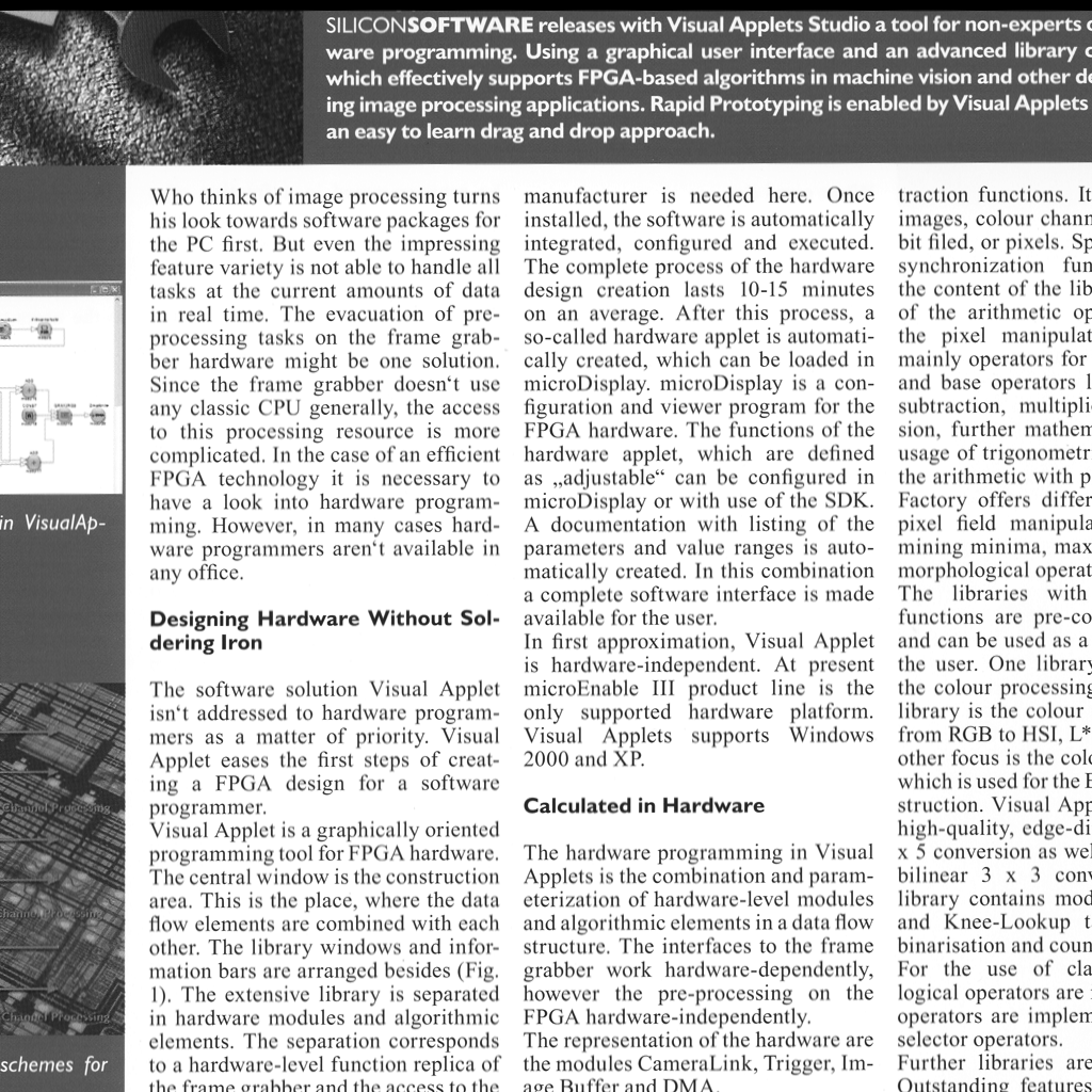
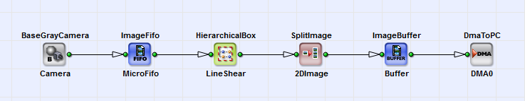
In Fig. 327 you can see the basic design structure: Every pixel of the 1D image from the camera operator is sheared in y direction in dependence on its x coordinate in the HierarchicalBox LineShear. The single lines are assembled to a 2D image with the operator SplitImage:2DImage. The corrected image is sent to PC via the operator DmaToPC .
In Fig. 328 you can see the content of HierarchicalBox LineShear. Here for every pixel the precedent N-1 line neighbors (here 31) are written in a Nx1 kernel.
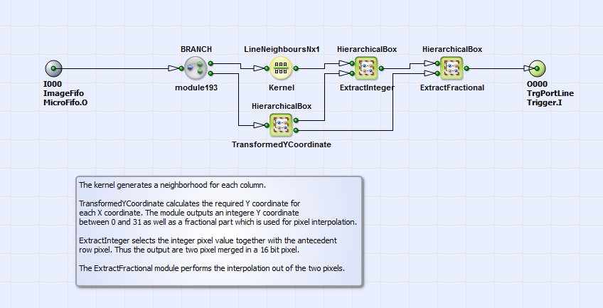
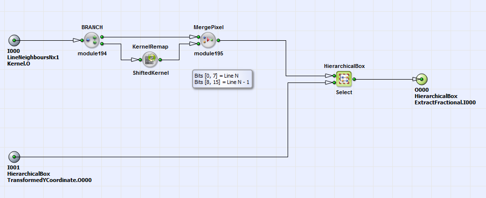
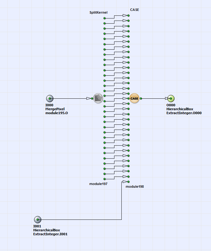
Each 8 bit pixel of this column is merged together with its preceding next neighbor (found with the operator KernelRemap:ShiftedKernel) into one 16 bit pixel. See therefore the content of HierarchicalBox ExtractInteger in Fig. 329. In the HierarchicalBox Select (see Fig. 330) the new pixel value for each pixel is selected with the operator CASE in dependence on the shifted (corrected) integer y position.
The corrected y position for each pixel is calculated in the HierarchicalBox TransformedYCoordinate (see Fig. 327). The content of this box is displayed in Fig. 331.
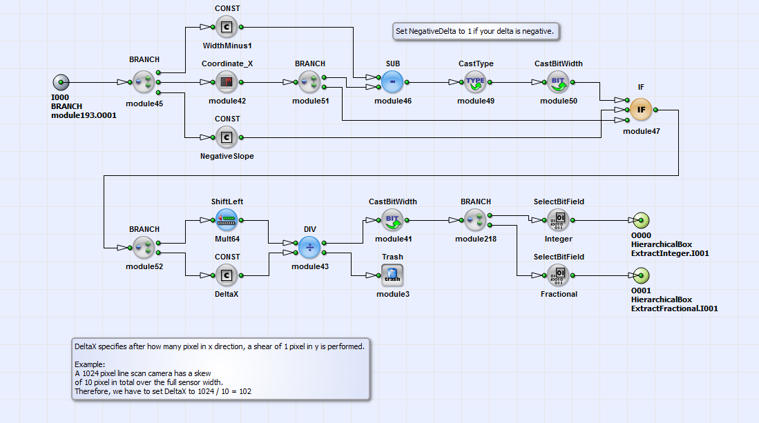
With the operator Coordinate_X the x position for each pixel is obtained.The possibility to "invert" the x position for negative skew slopes exist (selected with the operators Const: NegativeSlope and IF). With the operator CONST: DeltaX the misalignment of the camera is defined: This constant determines after how many pixels a one pixel shift in y direction is performed. With the operators SelectBitField: Integer and SelectBitField: Fractional the integer and fractional parts of the corrected y coordinate for every pixel are separated. In this example 6 fractional bits (see operator ShiftLeft:Mult64) are determined. The fractional part of each y coordinate is necessary for the linear interpolation performed in the HierachicalBox Interpolation, contained in the box ExtractFractional (see Fig. 328). You can find closer information on the interpolation algorithm in the comment in the HierarchicalBox Interpolation in the example. In Fig. 332 you can see as a result of the described operations the corrected image.